Introduction to the IPsec Protocol
The IP security (IPsec) protocol consists of two main components:
-
The Encapsulating Security Payload (ESP) protocol securing the IP packets transferred between two IPsec endpoints.
-
The Internet Key Exchange Version 2 (IKEv2) auxiliary protocol responsible for the mutual authentication of the IPsec endpoints and the automated establishment of encryption and data integrity session keys for both the IKev2 management protocol itself and for the ESP payload protection.
We do not treat the authentication-only Authentication Header (AH) protocol which is rarely used, especially because it is not suited for NAT traversal.
Encapsulating Security Payload (ESP)
The Encapsulation Security Payload (ESP) is defined in RFC 4303,
has IP protocol number 50 and doesn’t have any ports. ESP allows the encryption
of IP packets on the network layer carrying e.g. Layer 4 TCP traffic

IPsec Transport Mode
In IPsec Transport mode the original IP header is retained and just the Layer 4 payload carried by the IP packet is encrypted. The ESP header is inserted between the original IP header and the encrypted payload.
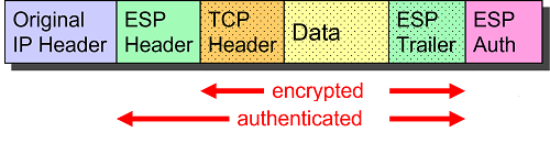
Originally intended for protecting direct IPv6 host-to-host connections, transport mode is currently mainly used to secure the Layer 2 Tunneling Protocol (L2TP), see RFC 3193.
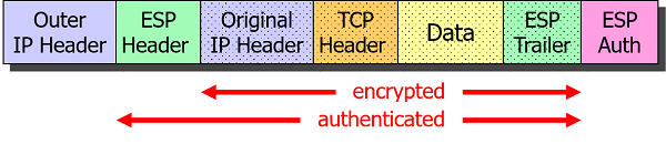
IPsec Tunnel Mode
In IPsec Tunnel mode the complete IP packet is encapsulated by ESP and an outer IP header is prepended:
ESP Packet Structure
An ESP packet consists of an ESP header, the encrypted IP payload body and an ESP trailer needed for padding. The Authentication Data field appended at the end as a cryptographic checksum guarantees data integrity.
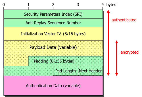
The 32 bit Security Parameters Index (SPI) is used by the receiving IPsec peer as an index into its kernel-based database to look up the session keys needed to decrypt and authenticate the ESP packet. The SPI is also needed to determine the IPsec security policy that has to be enforced on the inbound plaintext IP packets after decryption.
Internet Key Exchange Version 2 (IKEv2)
Version 2 of the Internet Key Exchange (IKEv2) protocol defined in RFC 7296
manages the setup of IPsec connections. The IKEv2 auxiliary protocol uses UDP
datagrams with both source and destination ports set to the well-known UDP port 500.
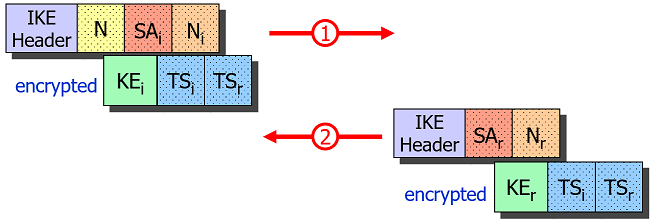
IKE_SA_INIT Request/Response
The Initiator starts the negotiation be sending an IKE_SA_INIT request which
is answered by the Responder with an IKE_SA_INIT response.

If the Responder comes to the conclusion that it is under a Denial of Service
(DoS) attack, it can request a Cookie from the Initiator before sending the
computationally expensive Key Exchange (KE) payload in the IKE_SA_INIT response.
This effectively prevents IP spoofing.
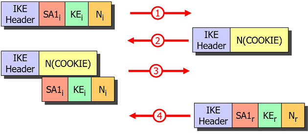
Based on the exchange of the Key Exchange (KE) and Nonces (N) payloads in
IKE_SA_INIT, both endpoints can derive a Shared Secret which allows them to
encrypt all following IKE messages based on the IKE_SA established via the SA1i
and SA1r Security Association payloads.
IKE_AUTH Request/Response
Certificate-based Authentication
In the ÌKE_AUTH request the Initiator authenticates itself by sending its
identity IDi and a Digital Signature in the AUTHi payload accompanied by an
optional Certificate payload CERTi. The Responder verifies the validity and
trustworthiness of the received end entity certificate by going up the X.509 trust
chain until a locally stored Root CA certificate is reached.
Additionally the Initiator sends a Security Association proposal SA2i and a
set of Traffic Selectors TSi and TSr to be used for the first CHILD_SA.
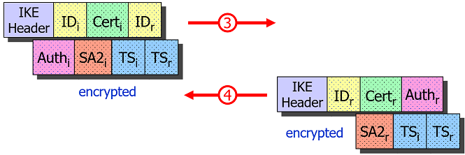
The Responder authenticates itself in turn with a Digital Signature in the
AUTHr payload accompanied by an optional Certificate payload CERTr contained
in the IKE_AUTH response and includes a selected Security Association SA2r
proposal and a possibly narrowed set of Traffic Selectors TSi and TSr.
With this information the CHILD_SA defining the encryption and data integrity
of the IPsec payload packets can be installed and activated.
PSK-based Authentication
If a Pre-Shared Key (PSK) is used for authentication then the AUTHi and AUTHr
payloads contain a hash over the exchanged IKEv2 messages and the pre-shared secret.
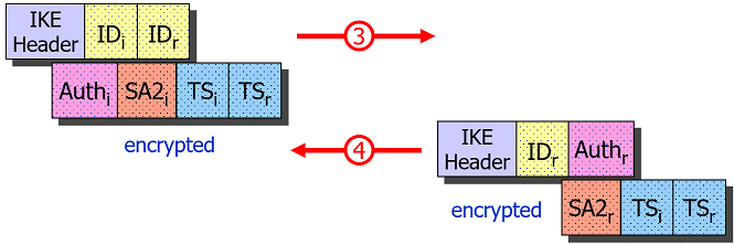
Since the Initiator is the first to send its password hash in the AUTHi payload,
this poses a serious security risk when the PSK is weak and is intercepted by an
active man-in-the-middle (MITM) who can then do an offline dictionary or brute force
attack on the AUTHi payload and potentially crack the password. Therefore we
strongly discourage the use of PSK-based authentication if a sufficient password
strength cannot be enforced.
EAP-based Authentication
In order to prevent man-in-the-middle-attacks possible with
PSK-based authentication, EAP-based authentication
has been introduced by the IKEv2 standard. If the Initiator doesn’t include an
AUTHi payload in the IKE_AUTH request, the Responder sends its strong Digital
Signature in the AUTHr payload first, in order to establish trust and at the
same time initiates the EAP protocol by including a first EAP request in the IKE_AUTH
response.
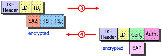
The Initiator can then use its PSK with EAP-MD5 or EAP-MSCHAPv2 to authenticate itself to the trusted Responder over the encrypted IKEv2 channel.
CREATE_CHILD_SA Request/Response
CREATE_CHILD_SA request/response pairs are used to negotiate additional CHILD_SAs
or to do the periodic rekeying of either the IKE_SA or the CHILD_SAs.
Without the N(REKEY_SA) notification the IKE_SA is rekeyed, the fresh
Key Exchange (KE) payloads guaranteeing Perfect Forward Secrecy (PFS). With a
N(REKEY_SA) notification included, a CHILD_SA is rekeyed, the Key Exchange
(KE) payloads being optional.
NAT Traversal
Since the ESP protocol with IP protocol number 50 doesn’t have any ports,
per se it is not suited for Port Address Translation, the standard method of
traversing a NAT router for the TCP and UDP protocols.
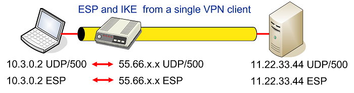
Some NAT routers have a feature, often called something like IPsec Passthrough that detects outbound IKE traffic from a single host behind the NAT device and will forward inbound IKE and ESP packets to that specific host as shown in the figure below
Unfortunately this won’t work with multiple IPsec clients behind the same NAT router that all want to communicate with the same VPN gateway as shown in the network topology below
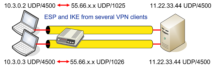
The solution proposed by RFC 3948 is to encapsulate ESP packets in
UDP datagrams which then allows to apply Port Address Translation as shown in
the figure above. The well-known NAT Traversal UDP port 4500 is shared with
the IKE protocol when a NAT situation is detected between
the two IPsec endpoints. The detection is based on the NAT_DETECTION_SOURCE_IP
and NAT_DETECTION_DESTINATION_IP notifications sent in the IKE_SA_INIT exchange
that contain source and destination IP address hashes, respectively.
ESP-in-UDP encapsulation can be enforced even if no NAT situation exists by setting
encap = yes for a given connection definition in
swanctl.conf. If enabled, the
charon daemon will send a manipulated
NAT_DETECTION_SOURCE_IP notify payload so that it will look to the remote peer
as if there were a NAT situation.
ESP-in-UDP Encapsulation
ESP-in-UDP encapsulation means that an eight octet UDP header is inserted between
the IP Header and the ESP Header of the ESP packet. At the outset the UDP source
and destination ports are both set to the well-known value 4500 but might get
changed on the way by one or several NAT routers.
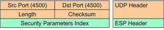
The first field in the ESP header right after the UDP header is the 32 bit non-zero Security Parameters Index (SPI).
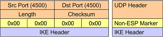
Non-ESP Marker
If the first 32 bits right after the UDP header are set to zero then instead of
an encapsulated ESP payload packet, an IKE management packet is carried. Thus this
four octet all-zero Non-ESP Marker is used to differentiate between ESP and IKE
traffic. ESP packets are processed in the kernel, whereas the IKE packets are
forwarded to the charon userland IKE daemon.
NAT-T Keepalives
When a NAT router applies Port Address Translation to an outbound IP packet, the address/port mapping is stored in an internal lookup table together with a time-to-live value. This mapping is needed by the router so that inbound IP packets can be translated back to the original address/port values.
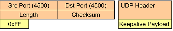
Since an established IPsec connection can be inactive for minutes or even hours,
the IPsec peer behind a NAT router has to send periodic NAT-T keepalive UDP
packets containing a single 0xff byte in order to refresh the NAT mapping entry
in the NAT router’s lookup table.
Of course the NAT-T keepalives also reach the IPsec peer on the other side of the
connection but the packets are silently dropped by the kernel. By default the
keep-alives are sent ever 20s but the interval can configured via the
charon.keep_alive parameter in
strongswan.conf (set to 0 to disable
sending keepalives, e.g. behind a static DNAT aka port forwarding).